
PCB depaneling is designed to deliver accurate PCB outlines, with all parts and joints intact, and that match or exceed the beat rate of the SMT lines they are integrated with. More than ever, depaneling systems are fully automated inline solutions rather than being operated offline in a batch process. Today depaneling machines are fully integrated and include robotic handling and full systems integration to the customer MES and other shop floor systems.
The router is the only process which actually removes material, and if improperly set up or incorrectly programmed, the router has the capacity to actually destroy a product beyond rework if it is misused or allowed to fall into disrepair. At the point an array of PCBs reach the depaneling system, all the PCBs physical value is close to maximized and the final task must perform. However the machine is only one factor that impacts the final outcome, and this too needs to be understood.
An important but often overlooked feature of depaneling is maintaining process control in respect to tooling and the consideration toward design for air flow and adequate support to negate the cutting forces of the process while accommodating the overall PCB thickness. This presentation considers the changing role of PCB routers in production as integrated facilities with full robotic handling, linked up and downstream to other hardware and software systems. It discusses the methods of assurance used by manufacturers at a factory level, and on site to ensure cutting performance as well as complete process control is maintained over the life of the machine. We will consider cutter compensation as a facility that may benefit the ultra-accurate but be overkill for others and what part vision systems play in adding value to the routing process.
Introduction
PCB Depaneling, Routing or Milling in many factories is either considered to be a stand alone operation supported by a manual operator feeding in Panels, retrieving cut PCBs and disposing of the scrap frame or it is an inline process that marks the termination of a line and an outfeed that is manually assisted.
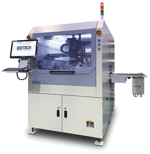
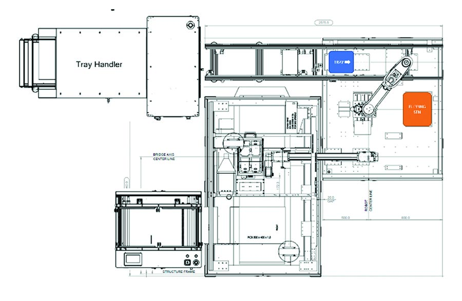
Fig 1. Today that is changing both in terms of automation, sorting and MES integration.
Production Considerations
Touchless Operations
In todays modern production environment workflows have become more continuous, allow few or zero human interventions and employ continuous product traceability and monitoring. They move information up and down stream, make adjustments and decisions affecting subsequent operations in the line in real time. Historically cooled PCBs would be racked in a magazine post reflow and taken to a batch routing process – or they would flow into an in-line routing system that would cut the PCBs from the panel and then offload them to a separate flat belt for manual loading to a tote, pallet or tray. In both scenarios humans are introduced to the workflow.
Product Traceability and Sorting
Product traceability is now an integral part of the business practices for most manufacturers and PCB routing systems have adapted to support these initiatives. Not only is a Panel ID read for the purposes of a date and time stamp but the machines functionality and its internal processes are mapped to any given panel, and panel data used to modify the machines programming.
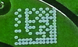
As an example the data from upstream testers can be conveyed to the router which reads the ID code from the panel Fig 2. as it enters the machine enabling closed loop communication with the factory MES.
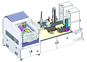
The factory data from upstream processes is matched via the MES and the router program modified on the fly to separate PCBs that have been tested Good/Bad at previous test stations. The Bad PCBs placed to a location for retrieval and analysis, Good PCBs placed to a downstream conveyance or storage system using such mechanisms as trays for storage or pallets for additive processing. Fig 3.
If a panel has individual ID codes on the PCB within the panel array, they too can each be read. The added bar code read will impact cycle time, so a method of matching data by association to the Master ID of the panel is more commonly adopted; with use of a cartesian map a single master code can be used to identify multiple individual PCBs while maintaining the data integrity and continuity without the impact of a cycle time reduction. With a master code tied to the all the child codes the panel entering the machine can be cut sorted and offloaded efficiently, the information related to the process recorded back to the MES with time and date stamps.
Machine design and Cutting
The first aspect of PCB routing that has to be recognized is it is an XY process involving material removal, most SMT processes are Z axis and material additive. The implication is on the machine structure and mechanical stiffness followed by peripheral equipment demands and how to manage them, the major one being vacuum and how to get cut material particulate away from the product and cutter.
The key elements of a router that have to be considered would include:
- Alignment method
- Cutting system and compensation
- Cleanliness
- Post cutting handling
- CFX / I4.0 for the future
Bare PCB Quality Control and Alignment
Every SMT process includes fiducial alignment and routers are no different, except the use of fiducial must be balanced with PCB fabrication and design expectations. EVERY customer wants a cut line to smoothly interface to the pre-route line left by the PCB fabrication house; not undercut which can result in a bump or overcut which will leaves a depression. The PCB fabrication house will likely stack multiple panels to gang cut the pre-route streets. During this process, the fab house do NOT typically use fiducials for alignment, but rather tooling holes. It is not uncommon for a pre route to be +/- 0.1 mm out of tolerance when measured from a fiducial. And we then have the panel complete the whole SMT process before it comes to the router, including the Reflow oven. FR4 is subject to warp and twist based on design, weight, copper load and so on. But the mechanical features can be significantly moved relative to the Fiducial references. The router will pattern match the fiducials based on the correction norms but cannot accommodate the shift if the material within that envelope are out of tolerance, and in this case fiducials may not always result in the smoothest cut to pre route. They will create a highly repeatable process that is fast and allows machines to be used that DO NOT require product specific fixtures.
Tool Wear and its impact
When a PCB does have to meet extremely accurate tolerances for cutting, not only is alignment key, but tool selection and the speed and feed rates used for the spindle RPM are critical. Cheap router bits will wear quickly and fail fast, a bit wears down 0.15mm diameter from start to finish, the net effect on the PCBs cut in that period will be the first panel processed is 0.15mm smaller at each tab than the PCB cut immediately prior to the bit failing, the finished product is 0.3mm bigger across its X and Y tab locations. A bit with a diamond pattern and no flutes will abrade the PCB, a fluted cutter will cut the material resulting in better surface finish and better dimensional stability. Thicker boards will flex less and be addressed more aggressively, thinner materials are easily deflected by a cutter and so need to be addressed more slowly and secured firmly.

Most machines today have Z axis tool compensation that enables the tool cutting surface to be used from its tip toward the shank. Fig 4. By shifting the Z axis up/down the thickness of the PCB every successive panel is cut on a different section of the tool, this results in longer tool life and better dimensional stability.
In cases where the stability of the cut dimension is paramount, two approaches can be considered.
1. Tool bit wear compensation: This uses previous characteristic wear data for a particular brand of tool and overlays it with the PCB cutting program and adjusts each new panel to accommodate for the wear that has occurred.
2. Bit – pre route vision alignment: Using a vision system to look at each tab and the line joining the pre route before and after the tab a line can be scribed that adjusts the actual program line to one that is individually created. But this method is extremely slow.
Dust Management
Having created the ideal cutting path and selected the very best cutting parameters based on material thickness, tab lengths and overall process requirements, the next consideration is what we do with resulting waste material. FR4 dust on the finished cut PCB is not acceptable, however removing the dust is not as simple as it sounds. FR4 dust is very fine and will cling to any surface it is able to contact, making its removal only possible with some mechanical agitation. Placing the vacuum manifold as close to the cutting tool as possible and supplying an adequate level of air flow in terms of volume and velocity is the only successful strategy. If your machine is top routing the vacuum needs to be connected to the cutting tool at the top side of the machine and visa versa. Vacuum systems through fixtures are wholly inadequate if quality and cleanliness are considered necessary. Within the vacuum system filtration systems suited to the particulate type are required and must be maintained on a regular basis.
Touchless Offload
With clean, cut PCBs, the machines role is moved to offloading the parts without human intervention to either the tray or pallet system. As previously mentioned, traceability can come to play where the tray or pallet has its own unique ID and that ID is tied to the parts placed in it. The benefit for carrier ID tracking is in noting pallets that may have issues and can be isolated by analysis or should a tray become separated from a batch and needs to be ID’d manually at a later point in the process, this is far simpler than scanning the trays contents looking for a particular batch of product.
Offload is the point in the process where sorting is managed, assuming a panel has bad PCBs and they have been ID’d via the MES they will have been cut. They are typically low in number and so can be placed to a dedicated reject area in the machine without taking up a great deal of space. Good parts are placed to the tray or pallet (Fig 5) system and moved down stream. As one tray leaves the system it is automatically replaced by the next.
Auto Change capability
With the panel now completely through the process lets assume the next panel on the inbound conveyor is for a different product. When the routing machine is of a type that does not need fixtures but uses a dual gantry structure with the cutting being done from below, the machine can auto change to accommodate the next product without any operator assistance. A bar code reads the Panel ID at the inbound conveyor and the machine automatically validates this with MES, once it is acknowledged the machine will adjust the conveyor rail, load the right cutting profile and select the correct top robot grippers for the width of the PCB being cut. Such capabilities make these machines highly flexible and suitable for smaller batch runs in lower volume higher value product lines. (Fig 6)
High Volume v Low
High volume can be accommodated in more traditional machine formats using top routing and two table configurations to allow the loading and unloading aspects of the cycle time to be absorbed within the cutting operations, thus creating highly efficient production machines. With these types of systems, dedicated fixtures cannot be avoided and so the cost and changeover time for such machines has to be considered when planning. Fixtures themselves can be identified by a 2D code and integrated into the Poke Yoke of machine and process management with Product and Fixture matching before cutting operations can begin.
Machine verification
The value of PCBs increases at every stage of the assembly process and by the time it reaches the router its value is close to maximized excluding any software or housing that may give it function and protection. Routing is the one process that could literally destroy the PCB if the tool were to deviate from its path and cut into the active circuitry, so having confidence in the machine and methods used to verify them is essential. Most modern routers use servo systems with a rotary encoded motion control for positioning and most have axis repeatability of +/-0.02mm and encoder resolution of +/-0.01mm. Machine structures and degree of stiffness may vary but before leaving the factory a machine should have undergone a basic Cmk analysis that confirms motion in X and Y axis is consistent and holds to the specifications prescribed by the machine manufacturer. Such tests can easily be replicated on site periodically and verified against prior data sets to confirm a machines long term stability.
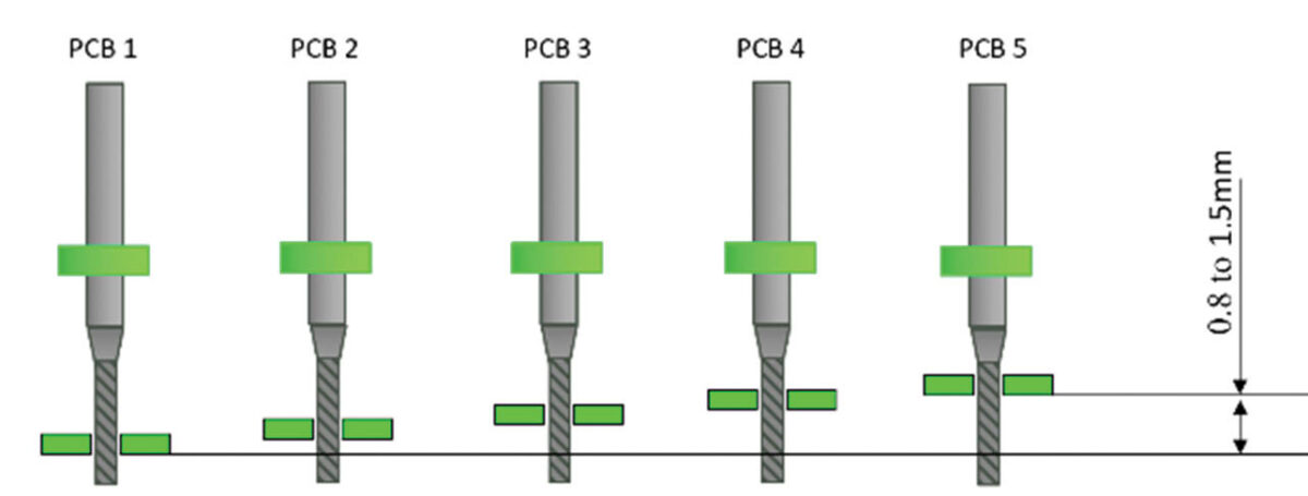
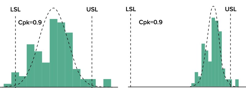
Product Cpk can be a misleading measure of a machines performance if the product being cut is prone to warp and twist and the mechanism
of measurement looks at cut to pre-route comparisons or compare cuts from the same location of PCB 1 to PCB 2,3,4,5,6, etc within the same panel.
The data could be impacted by mechanical creep within the panel itself and while the router program has NOT shifted the measured
results do. (Fig 7)
Conclusion
PCB routing has advanced significantly from being a simple cartesian motion system with a dremmel tool attached, being a batch process isolated from the main production line. The recognition of their value in both cutting PCBs, sorting and handling the completed product into its downstream carrier has brought considerable gains in efficiency and value to production lines globally.
Today with the advent of CFX and I4.0 we are now looking at real time feedback of axis data and other machine parameters providing a 3D view of the process on a per PCB basis. Stress and cleanliness remain a core requirement but by incorporating the downstream capabilities, the deliverables of a PCB router are significantly enhanced and a true “Touchless Process” from bare board to finished product, realized.
Read this article in i4.0Today magazine
